Sunday, 15 February 2015


Final project

·         Topology Diagram


Figure: Topology 

·         Addressing Table

Device
Interface
Ip address
Subnet mask
Default gatway
Sana’a
Fa 0/0.10
Fa 0/0.20
S0/0/0
S0/0/1.102
S0/0/1.103

192.168.1.65
192.168.1.81
64.1.1.1
10.1.1.1
10.2.2.1
255.255.255.240
255.255.255.248
255.255.255.252
255.255.255.252
255.255.255.252

ISP
S0/0/0
Fa0/0
64.1.1.2
172.16.1.1
255.255.255.252
255.255.255.0

Aden
Fa0/0
S0/0/0.201
192.168.1.1
10.1.1.2
255.255.255.224
255.255.255.252

Taiz
Fa0/0
S0/0/0.301
192.168.1.33
10.2.2.2
255.255.255.224
255.255.255.252

Web
NIC
127.16.1.10
255.255.255.0
127.16.1.1
FTP
NIC
192.168.1.20
255.255.255.224
192.168.1.1

Table 3.5: Addressing Table

·         Initial port assignments (switches access1 and access2)

Ports
Assignments
Networks
Fa0/1-6
Vlan 10 (IT)
192.168.1.64/28
Fa0/7-9
Vlan 20 (sales)
192.168.1.80/29
Fa0/24,23,22
Trunk 802.aq

Table 3.6: port assignments

Task 1: prepare the network
Step1: cable a network
Task2: perform basic router configuration
Configure the sana’a, aden , taiz, isp according to the following guidelines:
o   Hostname
o   Configure   a message-of- the-day banner
o   Configure   a password of sabafon123 for console connections
o   Configure   a password of sabafon123 for vty connection
o   Task3: perform switch configuration
Step1: create vlans on access1 and access2.
Step2: assign switch ports to vlans on access1 and access 2.
Step3 : configure trunk.
Step4: configure intervlan routing .
Step5: configure Ethernet channel.

Task4 : perform wan configuration
Step1: configure (point-to-point) frame relay between Sana’a ,Taiz and Sana’a Aden.
               
Task5: perform ip routing configuration
Step1: configure default static routing though s0/0/0 interface
Step2: configure EIGRP between Sana’a,Aden and Taiz

Task6: perform DHCP configurations
Step1: create four pools for
o   IT vlan (192.168.1.64/28)
o   Sales vlan (192.168.1.80/29)
o   Aden users (192.168.1.0/27)
o   Taiz users (192.168.1.32/27)

Task7: perform NAT configuration
Step1: configure PAT on sana’a
Task8: perform ACL configurations
Step 1: on router Sana’a deny IT users from accessing the ftp server using extended ACL.
Step2: on router Sana’a deny sales users from accessing web server using extended ACL .


·         Sanaa router configurations

version 12.4
no service timestamps log datetime msec
no service timestamps debug datetime msec
no service password-encryption
!
hostname sanaa
!
!
!
enable secret 5 $1$mERr$T62Fjzlp2XPRv5StN6Ke60
enable password sabafon123
!
!
!
ip dhcp pool IT
 network 192.168.1.64 255.255.255.240
 default-router 192.168.1.65
ip dhcp pool sales
 network 192.168.1.80 255.255.255.248
 default-router 192.168.1.81
!
!
!
username isp password 0 123
username sanaa password 0 123
!
!
!
!
!
no ip domain-lookup
!
!
spanning-tree mode pvst
!
!
!
!
interface FastEthernet0/0
 no ip address
 ip access-group 120 in
 ip nat inside
 duplex auto
 speed auto
!
interface FastEthernet0/0.10
 encapsulation dot1Q 10
 ip address 192.168.1.65 255.255.255.240
 ip access-group 110 in
!
interface FastEthernet0/0.20
 encapsulation dot1Q 20
 ip address 192.168.1.81 255.255.255.248
 ip access-group 130 in
!
interface FastEthernet0/1
 no ip address
 duplex auto
 speed auto
 shutdown
!
interface Serial0/0/0
 ip address 64.1.1.1 255.255.255.252
 encapsulation ppp
 ppp authentication chap
 ip nat outside
!
interface Serial0/0/1
 no ip address
 encapsulation frame-relay
!
interface Serial0/0/1.102 point-to-point
 ip address 10.1.1.1 255.255.255.252
 frame-relay interface-dlci 102
!
interface Serial0/0/1.103 point-to-point
 ip address 10.2.2.1 255.255.255.252
 frame-relay interface-dlci 103
!
interface Vlan1
 no ip address
 shutdown
!
router eigrp 20
 network 192.168.0.0 0.0.255.255
 network 10.2.2.0 0.0.0.255
 network 10.1.1.0 0.0.0.3
 network 192.168.1.0
 no auto-summary
!
ip nat inside source list 10 interface Serial0/0/0 overload
ip classless
ip route 0.0.0.0 0.0.0.0 Serial0/0/0
!
!
access-list 10 permit 192.168.1.0 0.0.0.255
access-list 130 deny tcp 192.168.1.0 0.0.0.255 host 64.1.1.2 eq www
access-list 130 permit ip any any
access-list 110 deny tcp 192.168.1.0 0.0.0.255 host 192.168.1.20 eq ftp
access-list 110 permit ip any any
!
banner motd ^C only authorized users can access ^C
!
!
!
!
line con 0
 password sabafon123
 login
!
line aux 0
!
line vty 0 4
 password sabafon123
 login
!
!
!
end
·         ISP  router configurations

version 12.4
no service timestamps log datetime msec
no service timestamps debug datetime msec
no service password-encryption
!
hostname isp
!
!
!
enable secret 5 $1$mERr$T62Fjzlp2XPRv5StN6Ke60
enable password sabafon123
!
!
!
!
!
!
username isp password 0 123
username sanaa password 0 123
!
!
!
!
!
no ip domain-lookup
!
!
spanning-tree mode pvst
!
!
!
!
interface FastEthernet0/0
 ip address 172.16.1.1 255.255.255.0
 ip nat inside
 duplex auto
 speed auto
!
interface FastEthernet0/1
 no ip address
 duplex auto
 speed auto
 shutdown
!
interface Serial0/0/0
 ip address 64.1.1.2 255.255.255.252
 encapsulation ppp
 ppp authentication chap
 ip nat outside
 clock rate 64000
!
interface Serial0/0/1
 no ip address
 shutdown
!
interface Vlan1
 no ip address
 shutdown
!
ip nat inside source static 172.168.1.10 64.1.1.2
ip nat inside source static 172.16.1.10 64.1.1.2
ip classless
ip route 0.0.0.0 0.0.0.0 Serial0/0/0
!
!
!
banner motd ^C only authorized users can access ^C
!
!
!
!
line con 0
 password sabafon123
 login
!
line aux 0
!
line vty 0 4
 password sabafon123
 login
!
!
!
End


·         Aden  router configurations
version 12.4
no service timestamps log datetime msec
no service timestamps debug datetime msec
no service password-encryption
!
hostname aden
!
!
!
enable secret 5 $1$mERr$T62Fjzlp2XPRv5StN6Ke60
enable password sabafon123
!
!
!
ip dhcp pool aden
 network 192.168.1.0 255.255.255.224
 default-router 192.168.1.1
!
!
!
!
!
!
!
no ip domain-lookup
!
!
spanning-tree mode pvst
!
!
!
!
interface FastEthernet0/0
 ip address 192.168.1.1 255.255.255.224
 duplex auto
 speed auto
!
interface FastEthernet0/1
 no ip address
 duplex auto
 speed auto
 shutdown
!
interface Serial0/0/0
 no ip address
 encapsulation frame-relay
!
interface Serial0/0/0.201 point-to-point
 ip address 10.1.1.2 255.255.255.252
 frame-relay interface-dlci 201
!
interface Serial0/0/1
 no ip address
 shutdown
!
interface Vlan1
 no ip address
 shutdown
!
router eigrp 20
 network 192.168.1.0 0.0.0.31
 network 10.1.1.0 0.0.0.3
 network 10.2.2.0 0.0.0.3
 no auto-summary
!
ip classless
ip route 0.0.0.0 0.0.0.0 Serial0/0/0.201
!
!
!
banner motd ^C only authorized users can access ^C
!
!
!
!
line con 0
 password sabafon123
 login
!
line aux 0
!
line vty 0 4
 password sabafon123
 login
!
!
!
end

·         Taiz  router configurations

version 12.4
no service timestamps log datetime msec
no service timestamps debug datetime msec
no service password-encryption
!
hostname taiz
!
!
!
enable secret 5 $1$mERr$T62Fjzlp2XPRv5StN6Ke60
enable password sabafon123
!
!
!
ip dhcp pool taiz
 network 192.168.1.32 255.255.255.224
 default-router 192.168.1.33
!
!
!
!
!
!
!
no ip domain-lookup
!
!
spanning-tree mode pvst
!
!
!
!
interface FastEthernet0/0
 ip address 192.168.1.33 255.255.255.224
 duplex auto
 speed auto
!
interface FastEthernet0/1
 no ip address
 duplex auto
 speed auto
 shutdown
!
interface Serial0/0/0
 no ip address
 encapsulation frame-relay
!
interface Serial0/0/0.301 point-to-point
 ip address 10.2.2.2 255.255.255.252
 frame-relay interface-dlci 301
!
interface Serial0/0/1
 no ip address
 shutdown
!
interface Vlan1
 no ip address
 shutdown
!
router eigrp 20
 network 10.2.2.0 0.0.0.3
 network 192.168.1.32 0.0.0.31
 no auto-summary
!
ip classless
ip route 0.0.0.0 0.0.0.0 Serial0/0/0
ip route 0.0.0.0 0.0.0.0 Serial0/0/0.301
!
!
!
banner motd ^C only authorized users can access ^C
!
!
!
!
line con 0
 password sabafon123
 login
!
line aux 0
!
line vty 0 4
 password sabafon123
 login
!
!
!
end

·         Access1 (Switch) configurations

Switch>en
Switch#conf
Configuring from terminal, memory, or network
[terminal]?
Enter configuration commands, one per line.  End with
CNTL/Z.
Switch(config)#ho
Switch(config)#hostname access1          
access1(config)#vlan 10
access1(config-vlan)#name IT
access1(config-vlan)#vlan 20
access1(config-vlan)#name sales
access1(config-vlan)#exit
access1(config)#int range f0/1-6
access1(config-if-range)#sw
access1(config-if-range)#switchport mo
access1(config-if-range)#switchport mode acc
access1(config-if-range)#switchport mode access
access1(config-if-range)#switchport access vlan 10
access1(config-if-range)#exit
access1(config)#int range f0/7-9
access1(config-if-range)#sw
access1(config-if-range)#switchport mode access
access1(config-if-range)#switchport access vlan 20
access1(config-if-range)#exit
access1(config)#end
access1#
%SYS-5-CONFIG_I: Configured from console by console

access1#show vlan b

VLAN Name                             Status    Ports
---- -------------------------------- ---------
-------------------------------
1    default                          active    Fa0/10,
Fa0/11, Fa0/12, Fa0/13
                                                Fa0/14,
Fa0/15, Fa0/16, Fa0/17
                                                Fa0/18,
Fa0/19, Fa0/20, Fa0/21
                                                Fa0/22,
Fa0/23, Fa0/24
10   IT                               active    Fa0/1,
Fa0/2, Fa0/3, Fa0/4
                                                Fa0/5,
Fa0/6
20   sales                            active    Fa0/7,
Fa0/8, Fa0/9
1002 fddi-default                     active   
1003 token-ring-default               active   
1004 fddinet-default                  active   
1005 trnet-default                    active   
access1#


·         Access2 (Switch) configurations same as access1 except hostname and for the trunk is as down

access2(config)#int range f0/23-24
access2(config-if-range)#switchport mode trunk
access2(config-if-range)#
%LINEPROTO-5-UPDOWN: Line protocol on Interface
FastEthernet0/23, changed state to down

%LINEPROTO-5-UPDOWN: Line protocol on Interface
FastEthernet0/23, changed state to up

%LINEPROTO-5-UPDOWN: Line protocol on Interface
FastEthernet0/24, changed state to down

%LINEPROTO-5-UPDOWN: Line protocol on Interface
FastEthernet0/24, changed state to up

access2(config-if-range)#channel-group 1 mode active
access2(config-if-range)#
Creating a port-channel interface Port-channel 1

%LINEPROTO-5-UPDOWN: Line protocol on Interface
FastEthernet0/23, changed state to down

%LINEPROTO-5-UPDOWN: Line protocol on Interface
FastEthernet0/23, changed state to up

%LINEPROTO-5-UPDOWN: Line protocol on Interface
FastEthernet0/24, changed state to down

%LINEPROTO-5-UPDOWN: Line protocol on Interface
FastEthernet0/24, changed state to up
access2(config-if)#exit
access2(config)#int port-channel 1
access2(config-if)#switchport mode trunk
access2(config-if)#end

access1#show etherchannel summary
Flags:  D - down        P - in port-channel
        I - stand-alone s - suspended
        H - Hot-standby (LACP only)
        R - Layer3      S - Layer2
        U - in use      f - failed to allocate
aggregator
        u - unsuitable for bundling
        w - waiting to be aggregated
        d - default port


Number of channel-groups in use: 1
Number of aggregators:           1

Group  Port-channel  Protocol    Ports
------+-------------+-----------
+----------------------------------------------

1      Po1(SU)           LACP   Fa0/23(P) Fa0/24(P)


Friday, 6 February 2015


Step 4: Vlan Routing  
Router(config)#int f0/0.3
Router(config-subif)#
%LINK-5-CHANGED: Interface FastEthernet0/0.3, changed state to up

Router(config-subif)#en
Router(config-subif)#encapsulation dot
Router(config-subif)#encapsulation dot1Q 3
Router(config-subif)#ip add 192.168.1.1 255.255.255.192
Router(config-subif)#exit
---------
Router(config)#int f0/0.2
Router(config-subif)#
%LINK-5-CHANGED: Interface FastEthernet0/0.2, changed state to up

Router(config-subif)#en
Router(config-subif)#encapsulation dot
Router(config-subif)#encapsulation dot1Q 2
Router(config-subif)#ip add 192.168.1.129 255.255.255.192
Router(config-subif)#exit
----------
Router(config)#int f0/0.5
Router(config-subif)#
%LINK-5-CHANGED: Interface FastEthernet0/0.5, changed state to up

Router(config-subif)#en
Router(config-subif)#encapsulation d
Router(config-subif)#encapsulation dot1Q 5
Router(config-subif)#ip add 192.168.1.65 255.255.255.192
Router(config-subif)#exit
Router(config)#do wr
Building configuration...
[OK]
-----------
Router(config)#int f0/0.5
Router(config-subif)#
%LINK-5-CHANGED: Interface FastEthernet0/0.5, changed state to up

Router(config-subif)#en
Router(config-subif)#encapsulation d
Router(config-subif)#encapsulation dot1Q 5
Router(config-subif)#ip add 192.168.1.65 255.255.255.192
Router(config-subif)#exit
Router(config)#do wr
Building configuration...
[OK]


Step 5: Verification commands
Router>enable
Router# show run
interface FastEthernet0/0
 no ip address
 duplex auto
 speed auto
!
interface FastEthernet0/0.2
 encapsulation dot1Q 2
 ip address 192.168.1.129 255.255.255.192
!
interface FastEthernet0/0.3
 encapsulation dot1Q 3
 ip address 192.168.1.1 255.255.255.192
!
interface FastEthernet0/0.5
 encapsulation dot1Q 5
 ip address 192.168.1.65 255.255.255.192
!

Note: in switch (1) where router is connected via fa0/20
1#conf t
1(config)#int  f0/20
1(config-if)#switchport access mode
1(config-if)#switchport mode trunk


Sunday, 1 February 2015

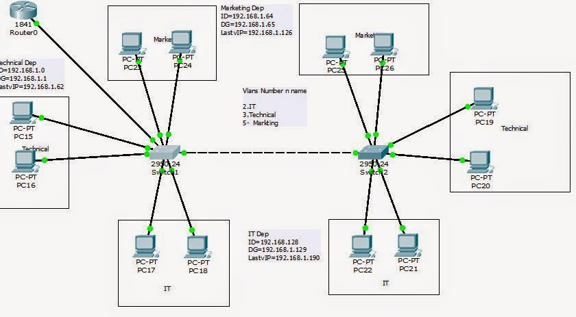
What has been done from VLAN,is illustrated as follows: 

Vlan_No
Vlan_Name
Switch Name
Port  Assignments
Network
Trunk
2
IT
1
Fa0/3, Fa0/4
192.168.1.128/26
-
3
Technical                       
1
Fa0/1, Fa0/2
192.168.1.0/26
-
5
Marketing
1
Fa0/5, Fa0/6
192.168.1.64/26
-


1-2
Fa0/10

Trunk
2
IT
2
Fa0/3, Fa0/4


3
Technical                       
2
Fa0/1, Fa0/2


5
Marketing
2
Fa0/5, Fa0/6


Switch 1
Step 1: Vlan creation
Switch>en
Switch#conf
Configuring from terminal, memory, or network [terminal]?
Enter configuration commands, one per line.  End with CNTL/Z.
Switch(config)#
Switch(config)#hostname 1
1(config)#vlan 2
1(config-vlan)#name IT
1(config-vlan)#vlan 3
1(config-vlan)#n              
1(config-vlan)#na
1(config-vlan)#name Technical
1(config-vlan)#vlan 5
1(config-vlan)#name Marketing
1(config-vlan)#do wr …………..> To save configurations
  
Step 2: Port assignments
1(config)#int range f0/3-4
1(config-if-range)#switchport mode access
1(config-if-range)#switchport access vlan 2
1(config-if-range)#exit
1(config)#int range f0/1-2
1(config-if-range)#switchport mode access
1(config-if-range)#switchport access vlan 3
1(config-if-range)#exit
1(config)#int range f0/5-6
1(config-if-range)#switchport mode access
1(config-if-range)#switchport access vlan 5
1(config-if-range)#do wr
Step 3: Trunk port
1(config)#int  f0/10
1(config-if)#switchport mode trunk
1(config-if)#end
1# wr
-------------------------------------
Switch  2 : Rewrite the same configuration as in (1), except the switch hostname should be named as (2)
as well the trunk port, it’s enough to be configured in switch (1).


*What  left is Router configuration
For now i can ping between the same Vlan hosts in both switches like (IT switch 1&IT switch 2), However ping between two different Vlans like (Marketing and IT ) still need router configuration.

Sunday, 18 January 2015


11 January.2015 ............>22 January.2015

1-Designing two networks each network has 8 hosts.


First network 192.168.10.0/24
Default gateway 192.168.10.1
First static host 192.168.10.2 ....>DNS server
First D-ip address 192.168.10.3
Last  D-ip address 192.168.10.10
------------------------------------

Second network is 192.168.20.0/24
Default gateway 192.168.20.1
First static host 192.168.20.2 ....>DHCP server
First D-ip address 192.168.20.3
Last  D-ip address 192.168.20.10
--------------------------------


2-Dedicate one DHCP server for the both networks.
3-Dedicate one DNS server for the both networks.
4-Simulation tasks using packet tracer.
5- Discussion the configurations with my supervisor (Have not done yet).
Video Simulation  1


Video Simulation  2 


Friday, 16 January 2015


15 December.2014 ------->8 January.2015

I was assigned to do backup/restore router configurations ,but before doing these tasks, i had to explain to my supervisor the way and the commands used for accomplish the given tasks by doing simulation using packet tracer.
Outlines were given by my supervisor to be shown in my simulation:

 Part1:
-Router named as Sabafon
-Two differant networks  first is 192.168.1.0 /24
              Second is        192.168.2.0 /24
-Config TFTP_SERVER 192.168.1.10
-Config telnet with 0 5
- Access Sabafon Router from   192.168.2.2
-Copy config_File to TFTP_SERVER as (any name)
print screen the saved file in the TFTP.
----------------
part2:
-Change the name of the router to UTeM
-Restore the backedup conf to the router
print screen
------------
Simulation Video
---------------------------

Configuration commands
Router> enable
Router# conf t
Router(config)# hostname sabafon
sabafon(config)# int f0/0
sabafon(config-if)#ip add 192.168.1.1 255.255.255.0
sabafon(config-if)# no shutdown

sabafon(config-if)#int f0/1
sabafon(config-if)#ip add 192.168.2.1 255.255.255.0
sabafon(config-if)# no shutdown
sabafon(config-if)# exit
sabafon(config)# line vty 0 5
sabafon(config-line)# password utem
sabafon(config-line)#login
sabafon(config-line)#end
sabafon#write

-------------------------
Router (Run file) contents


version 12.4
no service timestamps log datetime msec
no service timestamps debug datetime msec
no service password-encryption
!
hostname sabafon
!
!
!
enable secret 5 $1$mERr$3HhIgMGBA/9qNmgzccuxv0
!
!
!
!
!
!
!
!
!
!
!
!
spanning-tree mode pvst
!
!
!
!
interface FastEthernet0/0
 ip address 192.168.1.1 255.255.255.0
 duplex auto
 speed auto
!
interface FastEthernet0/1
 ip address 192.168.2.1 255.255.255.0
 duplex auto
 speed auto
!
interface Vlan1
 no ip address
 shutdown
!
ip classless
!
!
!
!
!
!
!
line con 0
!
line aux 0
!
line vty 0 4
 password utem
 login
line vty 5
 password utem
 login
!
!
!
end


Sunday, 14 December 2014


Started from 7 December I attend supported course which is: Cisco Certified Network Associate (CCNA) Fast Track, as a recommended course from my supervisor.Then as i have been told, i will be assigned for new tasks which needs CCNA course to be solved...

Thursday, 4 December 2014


Follow survey...

Part 1
General overview about GSM wireless network
The GSM wireless network can be partitioned into two major segments which are:
-          Radio Access Network (RAN)
-          Core Network (CN)
Figure down explain more


The way of registering a handset in the GSM system works like explain down:
The handset listen for a SID (System identification number) which being broadcasted by the nearest BTS (Base transceiver station), while the BTS received SID, the handset send its IMEI (international mobile equipment identity) as well MIN (Mobile identity number) then goes through the BSC (base station controller ) where the transmission is determined whether it’s voice or data. The BSC and BTS together called BSS (Base station subsystem).
Then directly goes to the MSC (Mobile switching center) where subscribers get authenticated, validated also the process of subscribers database SIM details which are HLR (Home location register) and VLR (Visitor location register) get checks in here, so the time that subscriber services confirmed, it goes back to the handset the same way. Although these all happen so fast that customers don’t even notice.  
An alternate part in the system is the GMSC (Gateway Mobile Switching Center) which routes calls targeted to another carrier’s wireless network or the PSTN (Public Switch Telephone Network). Also there is a VLR (Visitor Location Register) which is used to load balancing as it stores subsets of information from the HLR when the subscriber is not in his home area.
For data service, GPRS (General Packet Radio Service), the SGSN (Serving GPRS Support Node) perform as the MSC, then goes to the GGSN (Gateway GPRS Support Node), then depending on the APN (Access Point Name), it will go out to the Internet in varied ways. For the APNs there are three which commonly used
-          GOAM.com: is used for plain text browsing and accesses the internet by WAP gateway.
-          Internet.com: used for HTML browsing, accesses the Internet by a NAT Server.
-          Media.com: used for multimedia messaging, accesses the Internet by a WAP Gateway, then a MMSC (Multimedia Service Centre) or SMTP server (for email).

Part 2
Analysis the survey to find a new antenna location at BIT BOS area in Sana’a:
Figure below shows BIT BOS area:


An antenna is one of the most critical issues in any RF communications system. The antenna performance determines the quality and the Continuum of data flow in both directions. Selection of the antenna is often deferred to the first phases of a program and the quality of the selection is usually driven by value (quality, performance and price) not by price. The actual performance of the antenna in the system is always verified until after the system is installed, if at all.
It is important to make a level of common understanding among the system designer, the system integrator, the user and the antenna supplier regarding the required antenna performance. The joint goal of this team is to maximize the performance of the total system while minimizing cost.
In here is outlining the major questions regarding antenna parameter which should be answered prior to making a final antenna selection.
First, what kind of radiation pattern is desired?
This is the first major of antenna selection. The only way to increase gain is to concentrate power in a narrower beam width .The narrower the beam width, the greater the gain of the antenna. A good conceptual example of this concentration is the vertical Omnidirectional antenna. It is used for line-of-sight communications with mobile stations.
Second, what is the maximum allowable VSWR?
VSWR (voltage-standing-wave-ratio) which represents the degree with which an antenna is "matched" to the system impedance. Most modern antennas do not require any tuning for o optimum performance. VSWR is one of the easiest parameters to measure and VSWR meters are becoming very popular antenna installation tools. Most modern antennas, receivers and transmitters are designed for peak performance when operating into a 50 Ohm transmission line. If the VSWR is too high, the transmitter power may be reduced as well as the strength of the received signal.
Third, what polarization is required?
The common types of system polarization are vertical, horizontal or elliptical. Selecting the proper polarization for the system can enhance the overall performance by minimizing the interference from adjoining systems. For example, by installing system orthogonal to other systems in the area, you can provide up to 20 dB of isolation
Fourth, where will the antenna be mounted?
 Real impact comes when estimate the total environment and whether the antenna will perform and survive once installed. Moreover, the impact of local zoning ordinances and regulations on installing antennas should not be underestimated. The integral strength of the design must be considered such as its ability to withstand wind, ice, heat or cold and other extremes. In addition assess the ability of the major components such as the feed, the radome and connectors to withstand stress.


Fifth, how to choose the appropriate location for outdoor antenna
1-      The location should be high so the signals can cover the wanted area.
2-      The location should be not in a crowded area due to the signal’s effects on the human being, if so’ the signal power should not be high.
3-       To avoid annoying interference happening, the used frequency slots must be deferent from any other frequency that can reach that area.
4-      The antenna carrying capacity is at most 16 users calling at the same time, means if the antenna location in crowded area we should lower the frequency signal power, so that allow to reuse the same frequency slot in new different area without happening interference: as the signal power of the first location could not reach to new location where same slot of frequency is used.

Sixth, the challenges that we faced during the survey is
1-      Locations owners afraid of the antenna side effects as well the neighbors, so we need to convince them that there is no side effects could happen.

Seventh, why do we need to establish new antenna and how to know that:
The need for establishing new antenna has come from variety reasons such as:
-          Overcrowded population, in the worse case of antenna’s capacity it become able to connect with 48 users all of them calling at the same time, here I meant antenna with three sectors so, the individual sector is able to be connected with 16 user.
-          Enhance indoor signaling.
-          High data traffic, this figured out by many ways, below is the technique that we performed  before the analysis data department decide to establish new antenna :

After every cellular network design and implementation there should be network evaluation ,and to do network evaluation there are many ways, the efficient one that we performed is evaluate the network by drive test.
 Drive test is, evaluation method performed in mobile radio networks regardless of technology GSM,LTE,CDMA..Etc this way used vehicle or motor to collect the data, the vehicle or the motor contains the measurement tools “Tems investigating software, GPS, two  mobile phones” which doing data collection for network ,then after collecting the data there is step called analysis. Drive test data analysis this step is to identify problems that network has such as dropped calls, interference, high data traffic …etc .
Drive test hardware and software used in the test:
·         Laptop or notebook or other similar device with Tems investigation software installed
·          Two mobile phone or at least one
·         One GPS
·         Scanner if there is or it’s optional
The following figure shows the Standard connections:


The main objective of this test is to collect data, the data is collected by collection software and store in one or more output files below is the figure shows the job for each connection:


·         GPS: collecting data of latitude and longitude of each point / measurement data, time, speed… etc.  It is also perfect as a guide for following the correct routes.
·         MS: mobile data collection, such as signal strength  etc
·         Scanner: collecting data throughout the network, since the mobile radio is a limited and does not handle all the necessary data for a more complete analysis.

The min required to do a drive test, is a mobile device with a Tems investigation software to collect data and a GPS. Currently, there are cell phones that do everything. They have a GPS, as well as a collection of specific software. They are very practical, but still quite expensive.
Drive test investigation are:
·         Integration of new Sites or change parameters of Existing Sites.
·         Performance network and analysis.
·         Comparing, for example between two GSM networks performance.

--------------------------------------------
References

1-vijay k garg wireless communication and networking
3-http://www.ascom.com/nt/en/index-nt/tems-products-3/tems-investigation-5.htm#overview

*For the videos and photos i will upload later coz i have problem with syncing videos form my phone*